Frame 06A hardware 2024
Iron Man MK3 Helmet
A wearable 3D-printed helmet with a servo faceplate and dimmable LED eyes
Build time
~ 8 hours
Skill range
Intermediate maker
The story
A 3D-printed, wearable MK3 helmet: tap a button and two micro servos swing the faceplate open while the LED eyes fade in, with a potentiometer for brightness. After building mine I wrote the whole thing up as a full guide covering print settings, wiring, the Arduino sketch, sanding, and paint, then ran it as a workshop build others could follow at the Maker Hub.
Quick steps
- Print the sizing ring and verify ear clearance.
- Batch print panels and fit-critical parts.
- Upload the Arduino sketch to a Nano Every.
- Bench test servos, LEDs, and dimmer before install.
- Dry-fit shell + faceplate and dial servo links.
- Sand, prime, paint red/gold, then clear coat.
- Glue seams, add hardware, padding, and straps.
- Suit up and enjoy the arc-reactor vibes.
Sizing the helmet
- Print the sizing ring included with the model.
- Test fit. Light resistance over ears = perfect.
- Scale the shell up/down evenly and reprint if needed.
- Do not scale precision parts: brain_base, brain_cap, dimmer_arm, dimmer_mount, ServoArm_active, ServoArm_passive.
- Need battery clearance? Use the Dome_04-Resize insert.
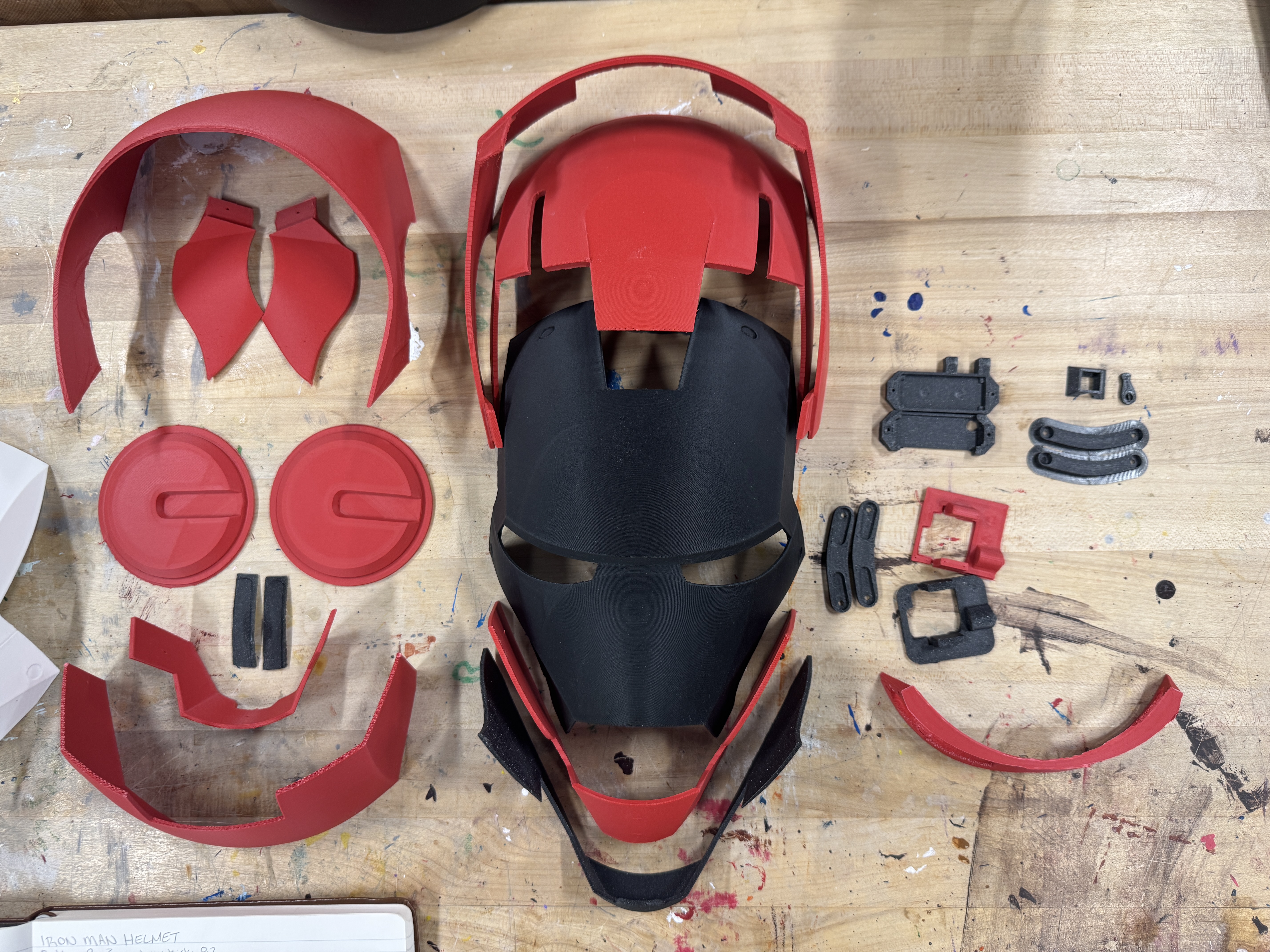
Printed parts list
- Bolt x8
- Brain_base, Brain_cap
- CheekL, CheekR, Chin
- Dimmer, Dimmer_arm, Dimmer_mount
- Dome_01, Dome_01-trenchL, Dome_01-trenchR
- Dome_02, Dome_03, Dome_04
- EarL, EarR, Eyes, Face, Jaw, Mouth
- ServoArm_active, ServoArm_passive
- ServoMount_face, ServoMount_head, Visor
Hardware and electronics
Electronics
- Arduino Nano Every
- ES08MA micro servos x2
- LED eyes (strip or custom PCB)
- 10k potentiometer for brightness
- 3-pin slide switch + momentary push button
- AAA battery pack (4-cell)
- Jumper wire kit, 2x 2x6x2.5 mm bearings (optional)
Assembly
- CA glue / Weld-On 16 for seams
- Elastic head strap + padding kit
- Sandpaper (120-400 grit) + filler primer
- Metallic red & gold spray paint + clear coat
- Clamps or painter's tape
- M2 & M2.5 hardware assortment, self-tapping screws
Arduino code
Upload this sketch with the ServoEasing library installed. Tune the open/closed constants to your servo geometry.
#include "ServoEasing.h"
ServoEasing servoTop;
ServoEasing servoBottom;

const int action_pin = 2; // trigger/proximity input (pullup)
const int ledPin = 6;     // eyes
const int potPin = A0;    // dimmer

int location = 31;
int bottom_closed = 107;
int top_closed = 167;
int bottom_open = 20;
int top_open = 20;
int value;
int maxBrightness;

void setup() {
    pinMode(action_pin, INPUT_PULLUP);
    pinMode(potPin, INPUT);
    servoTop.attach(9);
    servoBottom.attach(10);
    setSpeedForAllServos(190);
    servoTop.setEasingType(EASE_CUBIC_IN_OUT);
    servoBottom.setEasingType(EASE_CUBIC_IN_OUT);
    synchronizeAllServosStartAndWaitForAllServosToStop();
}

void loop() {
    value = analogRead(potPin);
    maxBrightness = map(value, 250, 750, 0, 255);
    int proximity = digitalRead(action_pin);
    if (proximity == LOW) {
        if (location > bottom_open) {
            servoTop.setEaseTo(top_open);
            servoBottom.setEaseTo(bottom_open);
            synchronizeAllServosStartAndWaitForAllServosToStop();
            location = bottom_open;
            delay(10);
            analogWrite(ledPin, 0);
        } else {
            servoTop.setEaseTo(top_closed);
            servoBottom.setEaseTo(bottom_closed);
            synchronizeAllServosStartAndWaitForAllServosToStop();
            location = bottom_closed;
            delay(50);
            analogWrite(ledPin, maxBrightness / 3);
            delay(100);
            analogWrite(ledPin, maxBrightness / 5);
            delay(100);
            analogWrite(ledPin, maxBrightness / 2);
            delay(100);
            analogWrite(ledPin, maxBrightness / 3);
            delay(100);
            analogWrite(ledPin, maxBrightness);
            delay(100);
        }
    }
}
Upload via Arduino IDE: select "Arduino Nano Every" as the board, install ServoEasing, and tweak servo endpoints until the faceplate seals cleanly.
Wiring diagram and notes
Tap to view full size.
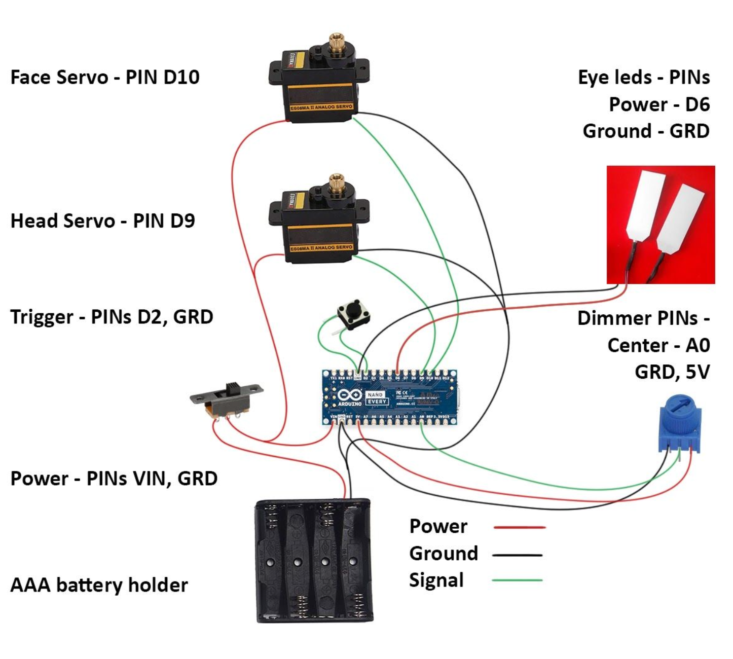
- Servos: signals on D9/D10, power from battery or regulated 5V, shared ground with Arduino.
- LED driver: PWM control on D6 (use a MOSFET if your LEDs pull real current).
- Potentiometer: wiper to A0, outer legs to 5V/GND.
- Faceplate trigger: normally-open momentary switch from D2 to ground with INPUT_PULLUP.
Dry assembly and alignment
- Mount servos to brackets and validate travel range on the bench.
- Dry-fit face + dome with painter's tape; cycle servos to confirm clearance.
- If you scaled the shell, mark and re-drill servo pivot holes to match.
- Use self-tapping screws for temporary alignment, then commit to CA/Weld-On.
Finishing
- Sand prints (120 to 220 to 400 grit) and apply filler primer between passes.
- Lay down metallic red on the shell and gold on the faceplate; finish with clear coat.
- Install padding, straps, and tuck wiring for a safe wearable fit.
Painting walkthrough: Smoothing & painting tips
Credits and references
This build consolidates guidance from Box and Loop, the Cults3D release, the Thingiverse remix, and the original Reddit thread. Huge thanks to the community for sharing designs and troubleshooting tips.
Stack · as built
Frontend
- 3D Printing
- Arduino Nano Every
- ServoEasing
Backend
- Electronics
- PWM Lighting
- Micro Servos
Infra
- PLA+
- Filler Primer
- Spray Finish
More prints
Want to build your own helmet?